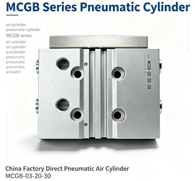
Finger pneumatic cylinders also belong to pneumatic actuating elements and are also a type of modified pneumatic cylinder. It can be used to grasp objects and perform various movements of the mechanical hand.
Structure diagram of the finger pneumatic cylinder

This diagram is the structural principle diagram of the finger pneumatic cylinder. When air is taken in through Port A and exhausts through Port B, the pneumatic cylinder piston rod 2 extends and rotates around the lever shaft 7 through the lever 3, driving two fingers 5 to move outward in a straight line on the guide rail 4 through a set of steel balls 11, thus opening the two fingers. Loosen the workpiece. The stop block 6 restricts the stroke of finger spread, and the positioning pin 13 ensures that the linear guide rail is not in position.
Tips for maintaining and caring for finger pneumatic cylinders
1. When the pneumatic cylinder is overhauled and reassembled, all parts must be thoroughly cleaned. Special attention should be paid to preventing the sealing ring from being sheared or damaged, and the installation direction of the dynamic sealing ring should be noted.
2. During use, it is necessary to regularly check whether there are any abnormal phenomena in all parts of the pneumatic cylinder and whether the connection parts are loose, etc. For the shaft pin type, the moving parts of the installed pneumatic cylinder should be lubricated with oil regularly.
3. When the pneumatic cylinder is disassembled and not in use for a long time, all processed surfaces should be coated with anti-rust oil, and dust-proof blocks should be added to the intake and exhaust ports.
4. When reassembling the pneumatic cylinder after maintenance, all parts must be thoroughly cleaned, and no dirt should be brought into the pneumatic cylinder. Special attention must be paid to preventing the sealing ring from being sheared or damaged, and the installation direction of the dynamic sealing ring should be noted.
5. Develop monthly, quarterly, and annual maintenance and servicing systems for the pneumatic cylinders, which can refer to the contents stipulated in the maintenance management system for directional valves.
Insights on the Installation and Process Performance of Finger Pneumatic Cylinders
1. Choose between parallel opening and closing type or fulcrum opening and closing type based on the size, shape, mas, and usage purpose of the work.
2. Select the series of pneumatic grippers based on the size, shape, overhang, usage environment, and purpose of the workpiece.
3. Select the size of the pneumatic gripper pneumatic cylinder based on the size of the particles held by the pneumatic gripper, the distance between the holding points, the overhang, and the stroke.
Above is Structure diagram of finger pneumatic cylinder, maintenance and installation process of finger pneumatic cylinder content, to learn more related information are available at https://www.joosungauto.com/.