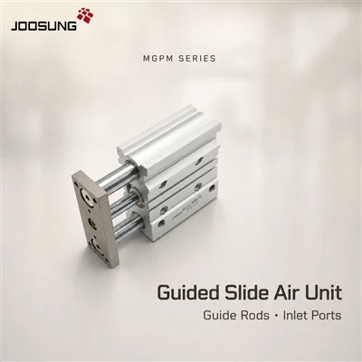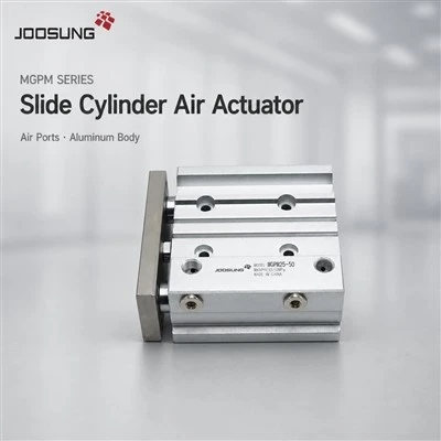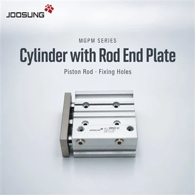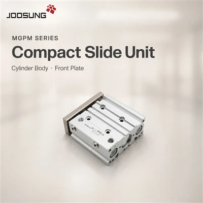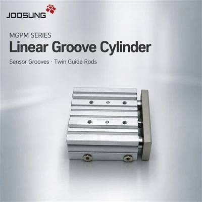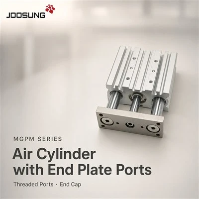
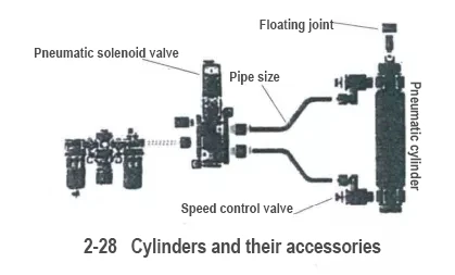
In the selection of pneumatic components, the cylinder is a key point, but the choice of accessories that go with it is not without care. For instance, solenoid valves, throttle valves, floating joints, etc., are all seemingly insignificant factors that affect performance.
(1)If there is any foolproof selection method for cylinder accessories, the selection table for cylinder accessories is one of them, as shown in Table 2-6. As long as the issue of selecting the actuator (cylinder) is resolved, the rest can basically be matched according to the table. For instance, once the CQ2-20-10 cylinder has been selected, it is very easy to choose other accessories, such as the solenoid valve SY3000 (or SY5000) series, the speed control valve (elbow type) AS2201F-M5-06, the floating joint JB20-5-030, and the pipe outer diameter Φ6mm, etc.
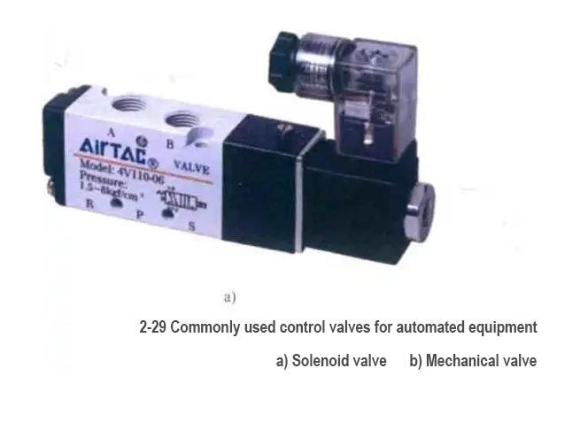
(2) Selection of Control Valves (solenoid valves) Control valves, like circuit switches (enabling the switching between current and off), play a role in switching the "on" and "off" states of the compressed air in the cylinder. Solenoid valves are the most commonly used in automated equipment (key point), and sometimes mechanical valves are also used, as shown in Figure 2-29.
Take the solenoid valve as an example. The selection process is shown in Figure 2.30, but in actual operation, it is rather formulaic. For instance, if the commonly used cylinder (cylinder diameter) does not change much, there is basically no need to repeat the selection of the solenoid valve every time.
The selection process of solenoid valves
Figure 2 · 30 Selection process of solenoid valves
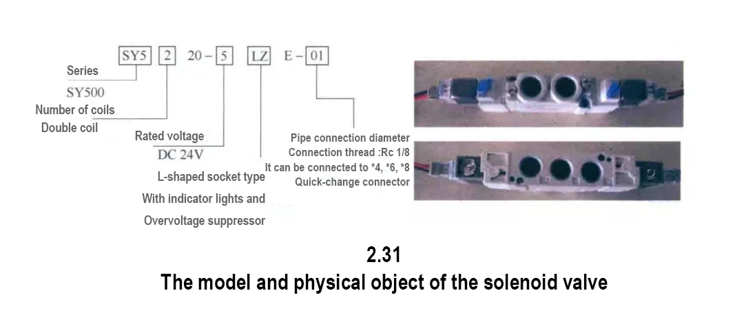
1) Solenoid valve model. The model and physical object of the solenoid valve are shown in Figure 2.31.
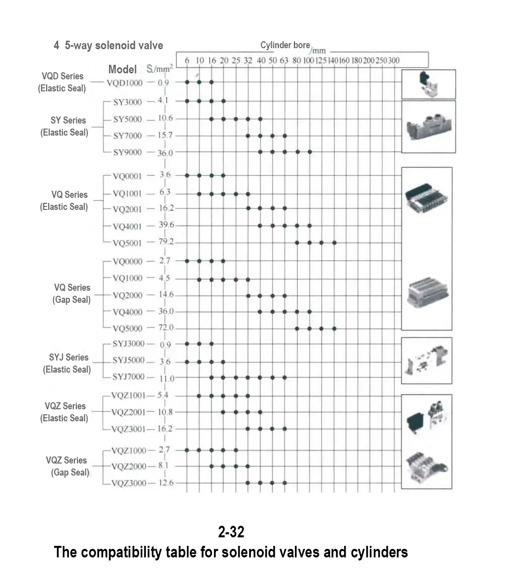
2) Solenoid valve series. The selection of solenoid valves is mainly based on the gas flow required for the operation of the cylinder (that is, on the one hand, it ensures that the effective area of the valve matches that of the working cylinder; On the other hand, when the working speed of the matching cylinder is met, for instance, when the working speed of the cylinder exceeds 300 to 500mm/s, the selection of the solenoid valve can be referred to in Figure 2-32. The cylinders used in electronic industry equipment are usually not large, so the SY series is the most commonly matched. If a large power is required, such as a cylinder with a diameter of Φ125mm, other series (such as the VQ series) can be selected.
3) Control function. There are two commonly used types of two-position five-way solenoid valves: single-coil and double-coil. Their control functions are different. Most of them adopt double-coil to prevent misoperation or safety accidents caused by equipment power failure, as shown in Table 2-7.
The model and physical object of the solenoid valve
Figure 2 · 31 Model and physical object of the solenoid valve
The compatibility table for solenoid valves and cylinders
Figure 2-32 Compatibility table of solenoid valve and cylinder
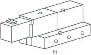
The piping forms of solenoid valves are as follows: a ') (a) direct piping type b) bottom plate piping type
Figure 2 · 33 Piping forms of solenoid valves a ') (a) Direct piping type b) Bottom plate piping type
Table 2.7 Switching Methods of Solenoid Valves
| Switch the party owner | Control content |
| Single coil at position 2 | After the power is cut off, restore the original position |
| Double coil at position 2 | When there is power supply on either side, return to the position on the side that provided power. When there is no power supply, maintain the position before the power outage |
4) For electromagnetic valves on electrical specification automation equipment, DC24V is more commonly used, and AC110V is also employed. In other cases, they are less frequently used, as shown in Table 2-8.
Table 2.8 Electrical Specifications of Solenoid Valves
| Types of current | Voltage | |
| Standard | Others | |
| AC (Exchange) | 110V,220V | 24V,48V,100V,200V, others |
| DC (Direct Current) | 24V | 6V,12V,48V, others |
5) Wire lead-out method. The wiring methods of solenoid valves include direct outgoing line type, L-type or M-type socket type, DIN socket type, and socket connection type. According to different occasions, the corresponding wiring method should be selected. Under normal circumstances, for small solenoid valves, direct outlet type and L-type or M-type socket type are chosen. Large solenoid valves are of direct outlet type and DIN socket type.
6) Piping form. There are two piping methods for solenoid valves: direct piping type and base plate piping type, as shown in Figure 2-33. Generally speaking, when there are many cylinders on the equipment, the bottom plate piping type is used, as shown in Figures 2.34 and 2-35. Multiple solenoid valves are connected together through busbars, and the busbars can also be connected in series. In this way, the gas path and wires are more concentrated, which is convenient for pipe laying and wiring.
The piping method for the base plate of solenoid valves (Part One)
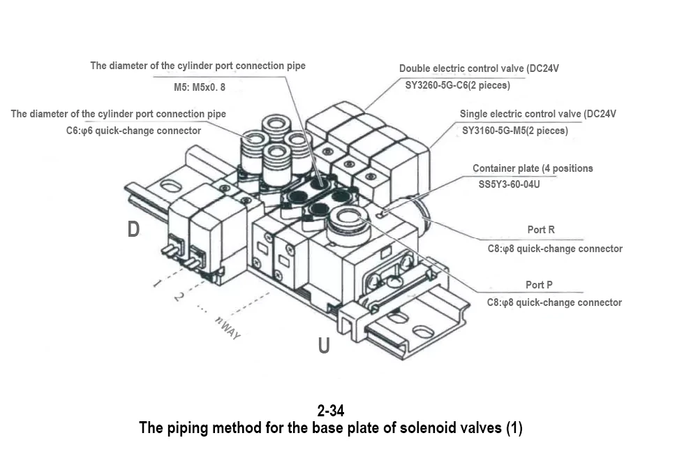
Figure 2-34 Piping Method for the base plate of Solenoid Valve (Part One)
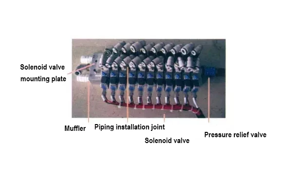
The piping method for the base plate of solenoid valves (Part Two)
Figure 2 · 35 Piping Method for the base Plate of Solenoid Valve (Part Two)
7) Pipe diameter. Each solenoid valve has its specified pipe diameter. Some may offer more than one diameter size to choose from. The specific size can be comprehensively considered based on the pipe diameter suitable for the actuator (refer to the relevant table in the catalog).
8) Optional (see Table 2-9)
Table 2.9 Options for Solenoid Valve Selection
| Project | options |
| Indicator light and overvoltage protection device | Equipped with indicator lights and overvoltage protection devices |
| The manual operation mode of the pilot valve |
Unlocked button type (standard) Screwdriver locking type Manual operation locking type |
(3) The selection of one-way throttle valves (also known as speed control joints or speed control valves) : The movement speed of the cylinder piston mainly depends on the flow rate of the compressed air input into the cylinder, the size of the cylinder's intake and exhaust ports, and the size of the inner diameter of the guide pipe. The movement speed of a cylinder is generally 50 to 1000mm/s. For cylinders with high-speed movement, an intake pipe with a larger inner diameter should be selected. When there is no requirement for speed regulation, a common quick coupling is selected. If speed regulation is needed, a speed-regulating coupling is generally chosen. The speed control joint is a flow control valve composed of a check valve (achieved by a one-way sealing ring) and a throttle valve in parallel. It has excellent flow characteristics and is mainly used to control the gas supply volume of the cylinder and other actuating elements (equivalent to controlling the speed). The internal structure is shown in Figure 2-36. For speed control joints of valve body M5 and below, gasket sealing is adopted, so there is no need to wrap sealing tape. However, for Rc thread occasions with valve body larger than M5, sealant is used. If it has been worn or fallen off (such as old speed control joints), sealing tape should be wrapped when used again; otherwise, air leakage may occur. When using sealing tape, the thread head should be left with 1.5 to 2 pitches. The winding direction of the sealing tape is shown in Figure 2-37. The speed-regulating joint is divided into two types: intake throttling and exhaust throttling, as shown in Figure 2-38. The so-called intake throttling means that the intake can be adjusted in size and the exhaust is not controlled. The so-called exhaust throttling indicates that the size of the exhaust gas can be adjusted and the intake gas is not controlled. The comparison is shown in Table 2-10. In most cases, an exhaust throttle valve is used (which has an advantage in performance, especially in horizontal movement scenarios). Of course, this does not mean that an intake throttle valve is useless. For instance, in a single-acting cylinder (spring return), if the extension speed is to be adjusted, it is necessary to hope that the intake (overcoming the elastic force to extend) can be adjusted in size. Using an exhaust throttle valve cannot achieve the purpose of speed regulation.
The internal structure of the speed-regulating joint and the winding method of the sealing tape
Exhaust throttle and intake throttle
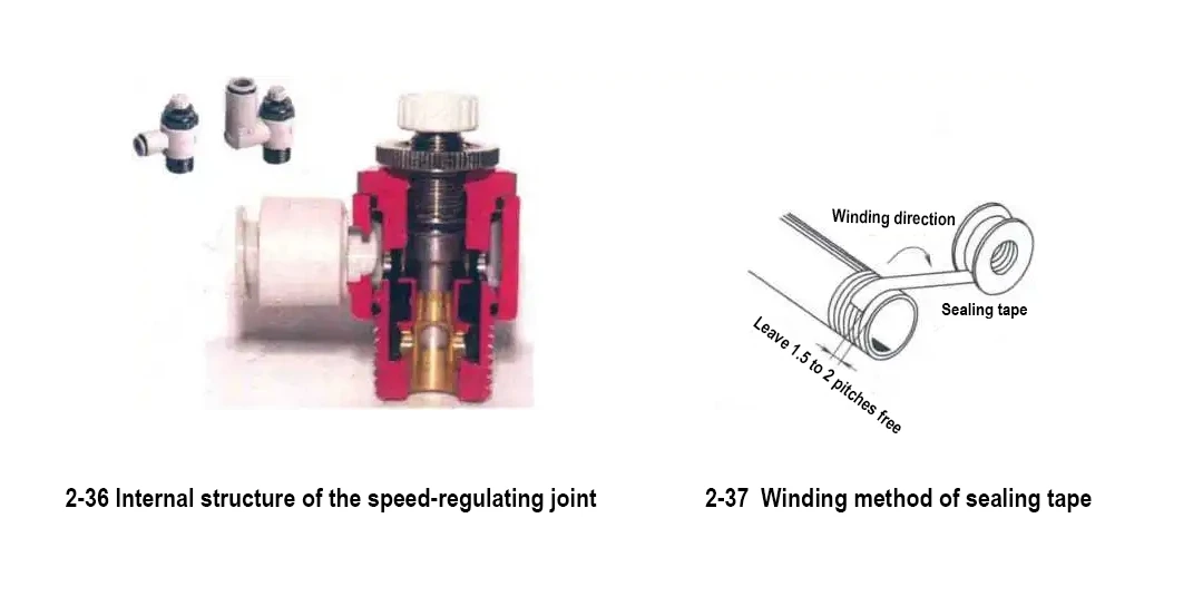
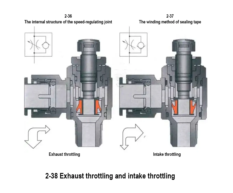
Figure 2.38 Exhaust throttling and intake throttling
Table 2.10 Comparison Table of Exhaust Throttling and Intake Throttling
| Characteristics | Intake throttling | Exhaust throttling |
| Low-speed smoothness | It is prone to low-speed crawling | good |
| The opening degree and speed of the valve | There is no proportional relationship. | There is a proportional relationship. |
| The influence of inertia | It has an impact on the speed regulation characteristics | It has little influence on the speed regulation characteristics |
| Starting delay | small | It is proportional to the load rate |
| Starting acceleration | small | big |
| Speed at the end of the journey | big | Approximately equal to the average speed |
| Buffering capacity | small | big |
It should be emphasized that when adjusting the speed of the actuator, the speed control joint should be gradually opened from the fully closed state to prevent the actuator from suddenly ejection. When tightening the lock nut of the speed control joint, it should be done directly by hand (do not use tools).
(4) Selection of other components (three-in-one combination, hydraulic buffer, floating joint, etc.)
Selection of other components
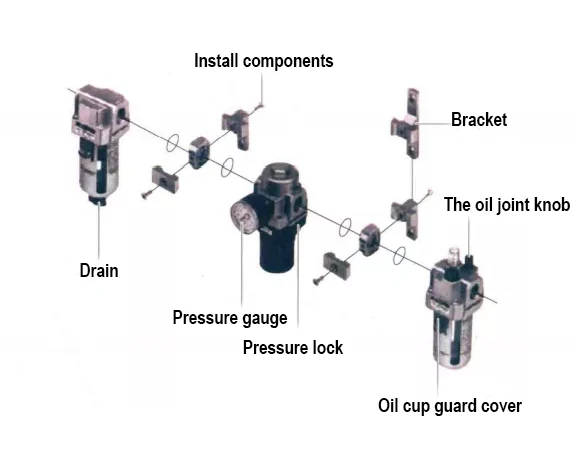
1) Three-in-one combination (Filler, Regulator, Lubricator,FRL). The compressed air output from the air compressor contains a large amount of pollutants such as moisture, oil and dust. Moisture has a significant impact on pneumatic components. It can cause rust on the metal of pipelines, water freezing, deterioration of lubricating oil and flushing away grease. Rust debris and dust can cause wear on relatively moving parts, accelerate the damage of seals, and lead to air leakage. Liquid oil, water and dust discharged from the exhaust port can pollute the environment and affect product quality. The three-in-one combination composed of an air filter, a pressure reducing valve and an oil mist lubricator (see Figure 2-39) can improve the quality of compressed air. Generally, each individual device needs to be equipped with it, as shown in Figure 2-40.
2) Floating joint. As shown in Figure 2.41, it is the link connecting the cylinder and the mechanism. It comes in various forms and can be purchased ready-made or made by oneself. It is not allowed to directly fix the cylinder rod on the moving part, as the cylinder may become eccentric or stuck, thereby accelerating wear (similar to the principle that a coupling is needed for the connection between an electric motor and a shaft). In actual design, self-made floating joints are more often used, as shown in Figure 2-42, which is similar to the design principle of the floating joint. It is to ensure that there is a non-rigid connection between the cylinder rod and the mechanism. However, it should be noted that when connecting the piston rod end of the SMC cylinder, a little attention should be paid to the thread specification. Internal threads are generally common coarse threads and can be fixed with ordinary screws or nuts. However, external threads are different from M10. The corresponding thread specifications need to be marked on the part drawing, such as ML0x1.25, M14X1.5, etc. To reduce the amount of workpiece rework, it is beneficial to frequently refer to the catalog. 3) Hydraulic buffer. When the cylinder stops at the end of its stroke, if there is no external brake or limiter, the piston and the end cover will generate an impact. To mitigate the impact force and reduce noise, a buffer device is generally required: for most cylinder action mechanisms, the (hydraulic) buffer shown in Figure 2-43 is used to reduce the impact and lower the noise. Some manufacturers have simply set a design standard that "all mechanisms with cylinder action must use buffers", which shows how much it contributes to the stability of the mechanism.
The three-in-one combination that each independent device needs to be configured with
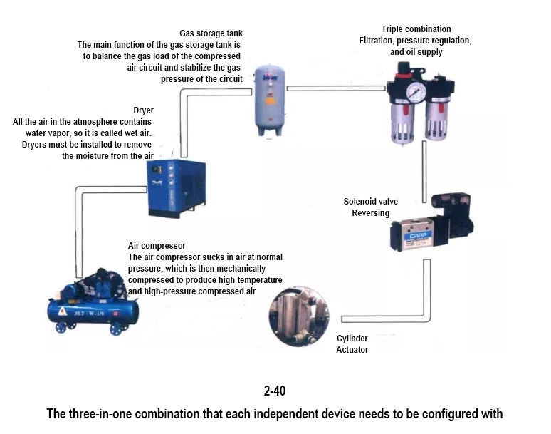
Figure 2-40 The three-in-one combination that each independent device needs to be configured
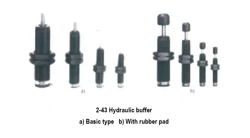
Figure 2-43 Hydraulic buffer
In fact, it is not necessary to use hydraulic buffers everywhere. Whether a buffer needs to be added mainly depends on the magnitude of the impact (related to kinetic energy, which is determined by the mass and speed of the object), rather than just the size of the cylinder. See Table 2-11.
Table 2.11 Buffer Forms and Their Applicable Situations
|
Buffer form |
Applicable circumstances |
|
No buffer |
It is suitable for micro cylinders, small cylinders and medium and small-sized thin cylinders |
|
Cushioning |
It is applicable to medium and small-sized cylinders with a cylinder speed not exceeding 750mm/s and single-acting cylinders with a cylinder speed not exceeding 100mm/s |
|
Air buffer |
Convert kinetic energy into pressure energy in a closed space, suitable for large and medium-sized cylinders with a cylinder speed not exceeding 500mm/s and small and medium-sized cylinders with a cylinder speed not exceeding 1000mm /s |
|
Hydraulic buffer |
It is converted into thermal energy and hydraulic elastic energy, and is suitable for high-precision cylinders with cylinder speeds greater than 1000min/s and those with relatively low cylinder speeds |
Above is How to choose cylinder accessories? Selection method of cylinder accessories,to learn more related information are available at https://www.joosungauto.com/.